


Why buy from us?
Lorem Ipsum is simply dummy text of the printing and typesetting industry.
Ask a Question About This Product
- Stock: In Stock
- Brand: OEM
- Model: DSJZ1047
- Location: https://detail.1688.com/offer/622326379888.html


 Micro 130 Small Motor, Four-Wheel Drive Vehicle Motor, Dc Small Motor, Small-Scale Production, Medium-Sized Motor")


FT2232HL development board/application board【Spot shooting】
Please read this detail page patiently; Please also refer to
FT2232HL can be used to convert from USB to various interfaces, such as UART/SPI/JTAG/I2C, etc.
Please refer to its datasheet for detailed functions of the chip.
[Description]
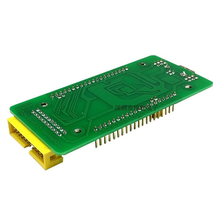
Overall dimensions (length x width x height): 103 x 45 x 14 mm
PCB size (length x width x thickness): 95 x 45 x 1.6 mm
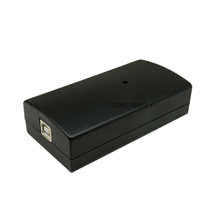
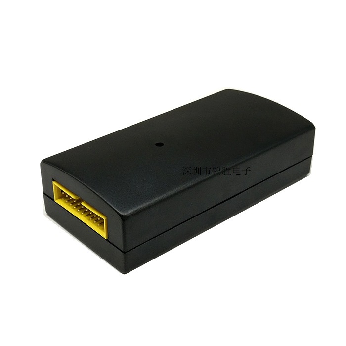
The whole board is suitable for installation inside common plastic shells.
Power supply method:+5VConnect to CN3 through a USB square port cable.
All functional pins are led out, making it convenient to connect peripheral modules using DuPont wires.
The signal pins of CN3 and CN4 are equipped with ESD protection circuits,Please refer to the schematic diagram for details.
CN1:2.54mm spacing 1 × 20 pins singlePin;
CN2:2.54mm spacing 1 × 20 pins singlePin;
CN4:2.54mm spacing 2 × 10 pins doubleEasy horn seat for bent needles.
The distance between CN1 and CN2 is 1400mil, which is 14 × 2.54=35.56mm.
【 Related Information 】
1. The schematic diagram of the board (address: https://github.com/arm8686/FT2232HL-Board ).
2. Please download the updated version of the chip documentation and drivers from the FTDI official website (official website address: http://www.ftdichip.com/ ).
3. Documents such as "FT2232HL as a Concise Handbook for OpenOCD V0.1. pdf"
Link: https://pan.baidu.com/s/1DYk8u500OdhF4Sqh5eX6Jg
Extraction code: paxb
For more usage and functions of FT2232HL, users need to understand the application documentation of FTDI company. Our store currently does not have relevant technical support.
【 Simple usage steps 】
LED1 is the power on indicator light. After power supply, it stays on continuously.
After installing its driver CDM21228_Setup, FT2232HL defaults to USB to dual serial port.
Using PC serial port debugging software can easily test these two serial ports.
Just use two DuPont wires for cross connection of the serial port:
ADBUS0 (TXD) connected to BDBUS1 (RXD)
ADBUS1 (RXD) connected to BDBUS0 (TXD)
U7 (74HC573) is connected to BDBUS for driving LED for signal indication.
When the board is powered on, some LEDs flash, which is a normal phenomenon.
When BDBUS is used as a serial port and turned on, the red light in LED5 remains on, which is an indication of hardware flow control and a normal phenomenon.
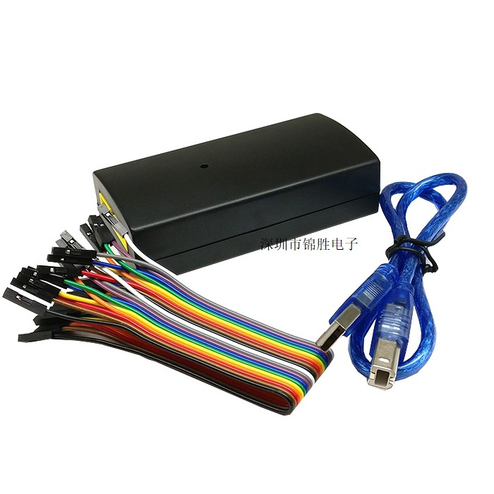
【 Shipping List 】
1. FT2232HL development board: 1;
2. USB square port cable (0.5m): 1 piece;
3. DuPont thread: 10 pieces;
4. Non silk screened plastic shell: 1 piece. (There is currently no self tapping screw, but the displacement that can be shaken after the board is placed in the shell)<2mm , Does not affect usage. )