


Wireless Battery Monitor Meter DC 120V 300A VOLT AMP AH SOC Remaining Capacity
Specifications:
- Item Type: MP3 Players Accessories Kits
- Function: Other
- Demo Board Type: ARM
- Compatible Devices Brand: Other
- Brand Name: HQXRTEK
Purchasing notice:
1. I hope you will download the instruction document before operating, you need the temperature function, and you need to add the temperature link.
2. The default version of the meter does not have a temperature measurement function, if you need to add a temperature sensor for temperature measurement function, you can click the option of "add temperature measurement function to make up the difference".
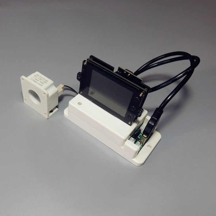
3. The power supply of the instrument display board can be used with an ordinary 5V power adapter (such as mobile phone charging head), or you can use the USB port on our measuring board to supply power to the display board, if the power supply voltage of the display board wants to change the range, please contact the seller in advance for instructions.
4. The instrument can realize automatic switching of charge and discharge through the charging and discharging relay interface with its own relay, and can also manually switch charging and discharging through the button.
5. The instrument has a total of 18 functional options, these 18 functions are based on the long-term accumulation of customer needs, each function helps customers to obtain more accurate measurement results more conveniently and quickly, here we briefly introduce the role of each functional option, the specific implementation method and operation steps can refer to the manual.
(1) NCP: Set the charging over-current protection value, and cooperate with the relay to realize the over-current protection during charging;
(2) OCP: Set the discharge over-current protection value, and cooperate with the relay to realize the over-current protection during discharge;
(3) OVP: set the charging overvoltage protection value (the voltage exceeds the set voltage can automatically fill up the capacity), and the relay can realize the automatic disconnection function when it is full;
(4) LVP: set the discharge overvoltage protection value, and cooperate with the relay to realize the automatic discharge disconnect function;
(5) OUT: By clicking OUT, the switching output function of the wireless control relay can be realized;
(6) LCK: key lock function, if necessary, the key can be locked to prevent misoperation;
(7) BAT: preset total battery capacity; as a reference value for the percentage of capacity;
(8) BPC: preset battery remaining capacity percentage and battery remaining capacity;
(9) CER: Current to 0 function, when the no-load current is not 0, you can click this option to clear the current to zero;
(10) RET: WH and running time value zeroing function, convenient for the next measurement;
(11) LNG: language switching function, this instrument has built-in Chinese and English two languages, and the language can be switched through this option;
(12) STI: Set the default state of relay power-on, open or closed;
(13) SFH: device search function, through which one-to-many communication can be done;
(14) DEL: set the relay delay working time; Realize the delay operation of the relay after protection
(15) FCH: communication address modification function, if multiple groups of modules at the same time, each group of modules should set different addresses to prevent interference;
(16) SNR: set the screen-off current, when the SNR is greater than 0, and the screen-off time value is not 0, the automatic screen-off function can be realized, and when the charging current is less than this value, the total charging capacity is not accumulated to avoid the impact of floating charge on the capacity value, and the LCD screen will automatically light up when the current is greater than this value.
(17) SNT: set the screen off time value, when the SNT value is 0, the LCD screen will never go out; When the SNT value is greater than 0 and the SNR is greater than 0, the screen can be automatically turned off and on.
(18) RFS: display color switching function, this instrument has two kinds of color matching, customers can choose different colors according to their preferences.
Notify:
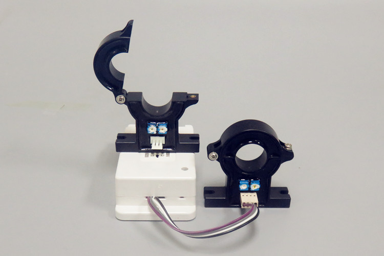
According to customer needs, our store has launched an open-ended Hall current sensor, which can directly replace the original current sensor, making the measurement current wiring more convenient, and saving manpower and time when replacing the measurement object.
1. Picture display


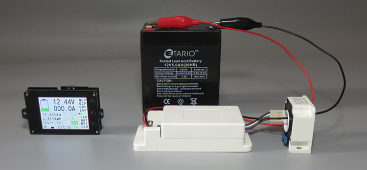
2. Introduction to the instrument
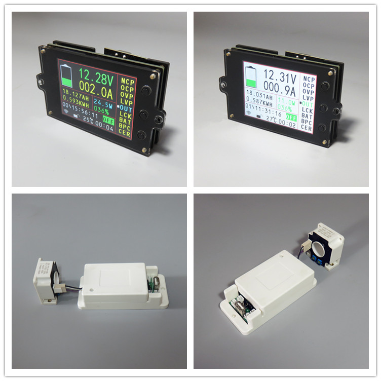
VAC8010F is a multi-functional instrument based on 2.4G wireless data transmission technology, which can display voltage, current, power, capacity, energy, temperature, running time and other physical parameters in real time, and can realize battery charging and discharge management and over-voltage, under-voltage and over-current protection respectively through the reserved two relay interfaces. Moreover, the instrument uses 2.4-inch color LCD as the display, which displays the data more comprehensively, clearly and easily observed.
Third, the main features
1. Wireless transmission of data, avoiding interference caused by complex wiring between the display and the detection module, and making the wiring more convenient.
2. The Hall sensor is used to realize non-contact detection current, without disconnecting the wire, which is safe, reliable and convenient.
3. Voltage, current, power, temperature, capacity, percentage of remaining capacity, and running time are displayed at the same time.
4. Dual relay interface, which can manage charging and discharging separately.
5. It has the protection functions of charge overvoltage, discharge undervoltage, charge overcurrent and discharge overcurrent.
6. Power-off memory function, after power-off, you can remember the number of AH and WH before power-off.
4- Fourth, technical indicators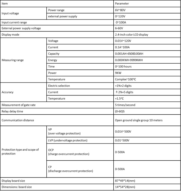
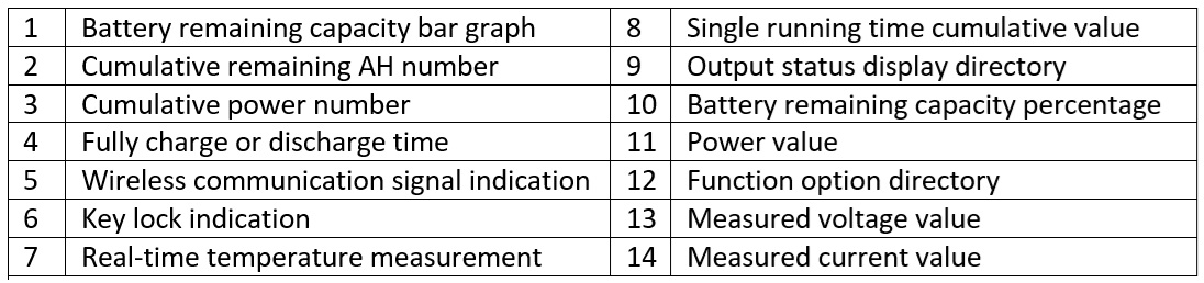
5. Panel description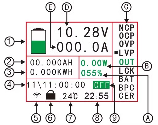
6. Description of the interface of the measuring board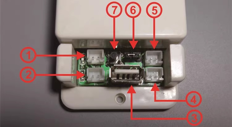
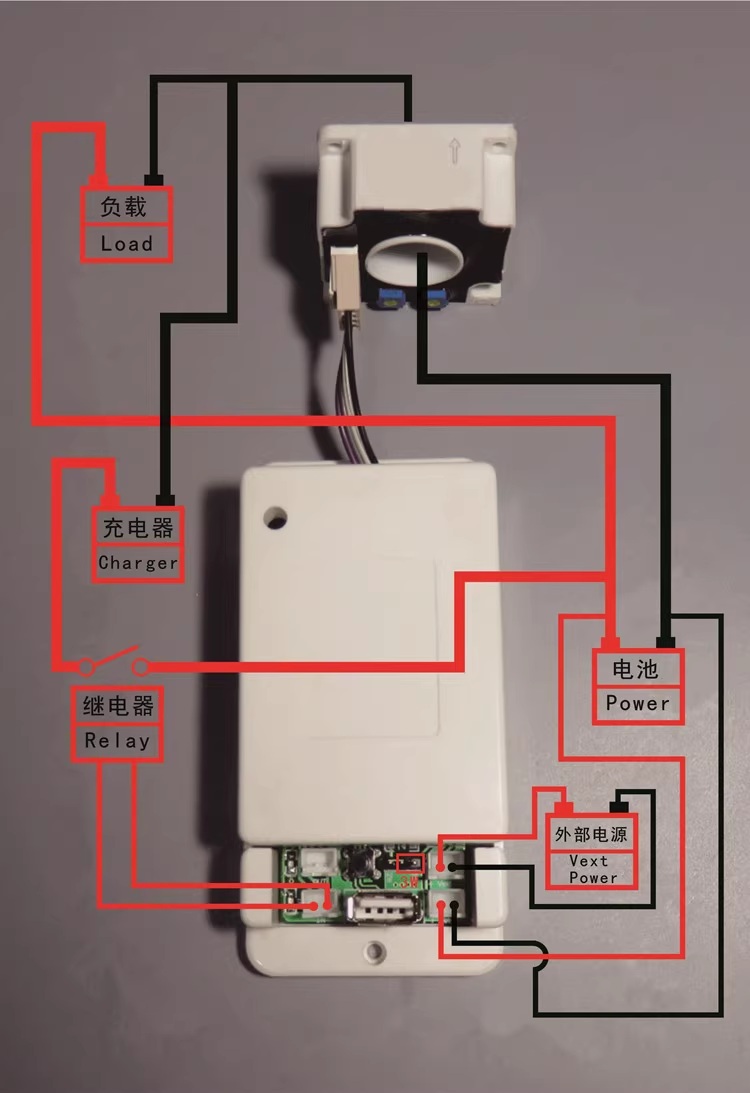
7. Wiring method
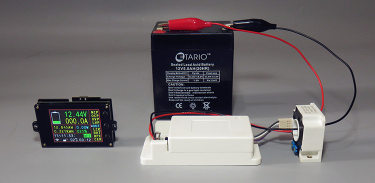
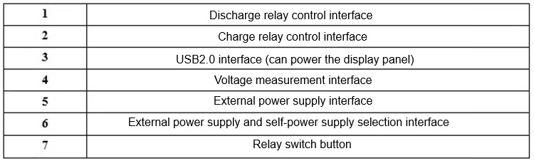
Note: If the voltage of the battery (power supply) under test is within the range of (6-80)V, the battery (power supply) can be used for its own power supply wiring, and if the voltage of the battery under test is greater than 80V or less than 6V, the external power supply wiring mode should be used; If the voltage is not in the range of (6-80)V, please do not use your own power supply, as this connection may damage the measuring instrument.
(1) Self-power supply wiring diagram
Note: If the voltage range of the tested battery (power supply) is between (6-80V) during normal operation, you can use its own power supply wiring, first adjust the jumper cap of the power supply selection interface to "2W", and then connect the positive and negative poles of the battery (power supply) to the voltage measurement port "+Bat-" when wiring; Note that "+" is connected to the positive pole of the battery (power supply), and "-" is connected to the negative pole of the battery (power supply), the positive and negative poles of the power supply should not be connected to the wrong or reversed, the positive pole of the battery (power supply) is connected to the positive pole of the load, and the negative pole of the battery (power supply) is connected to the negative pole of the load through the Hall sensor, when the direction of the current flowing through the Hall sensor is consistent with the direction of the electric arrow on the Hall sensor, the measured current will be displayed as a positive value, otherwise the measured current will be displayed as a negative value.
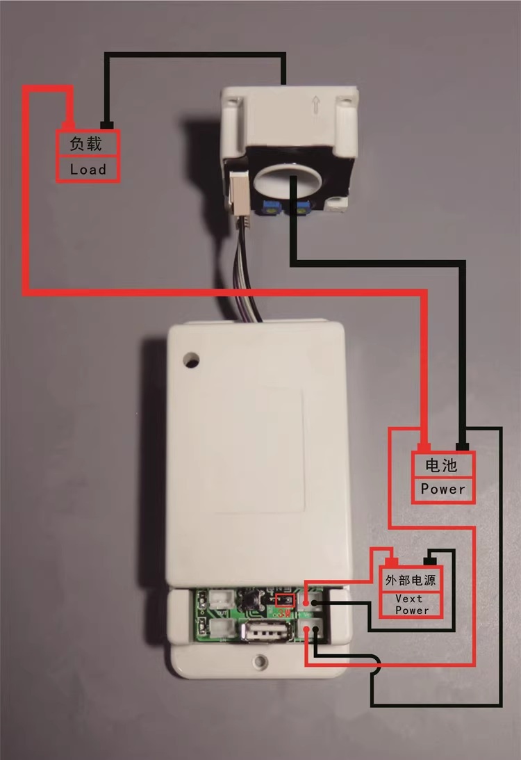
(3) Wiring diagram of discharge relay
Note: The working power supply of the relay is provided by an external power supply, and if the relay is connected, an external power supply with the same working voltage as the relay should be provided. Connect the control port of the relay to the interface of the discharge controller, if you want to control the positive pole of the discharge, pass the positive pole wire through the relay, if you want to control the negative pole of the discharge, connect the negative pole wire to the relay, when the relay is engaged, the "OUT" light will be lit up, and it will be extinguished as a prompt when it is disconnected.
4) Wiring diagram of the charging relayNote: The working power supply of the relay is provided by an external power supply, and if the relay is connected, an external power supply with the same working voltage as the relay should be provided. Connect the control port of the relay to the interface of the charge controller, if you want to control the positive pole of charging, pass the positive pole wire through the relay, if you want to control the negative pole of charging, connect the negative pole wire to the relay, when the relay is engaged, the "IN" light will light up, and it will be off as a prompt when it is disconnected.
- Stock: In Stock
- Model: ASKZS1142
- Weight: 0.20kg